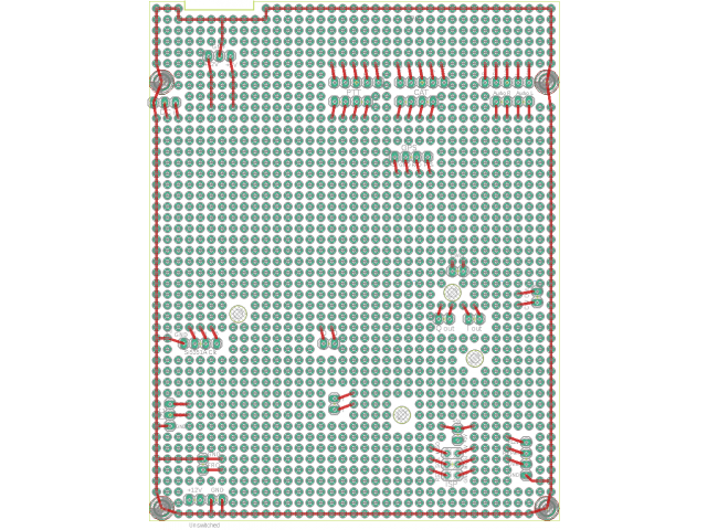
The QCX+ development board kit is for anyone who wishes to experiment or modify their QCX+. The development board kit consists of a kit of parts including a PCB with the following features:
- High quality, double-sided PCB sized 95mm x 120mm (see PCB CAD exported diagram in the photos above)
- Through-hole plated holes with solder pads on top and bottom sides, on a standard 0.1-inch (2.54mm) matrix
- Ring of holes around the outside edge are all connected to ground
- Holes in the PCB are drilled to allow a screwdriver adjustment of the C1 trimmer capacitor, and the three trimmer potentiometers
- holes for fitting pin header connectors that mate with connectors on the main QCX+ PCB, for:
a) Power (Gnd, +5V, 12V)
b) Si5351A Clk0/1/2 outputs)
c) I2C bus
d) ISP header
e) Frequency counter, DVM and RF Power inputs
f) I and Q outputs (IC5 pin 1 and 7)
g) I and Q path phase shift outputs
h) CW filter input and output
i) Audio amplifier input and output
j) GPS header
k) CAT control and PTT signals
l) All pins of the PTT, CAT and Audio connectors
The dev kit consists of the following items:
- 95 x 120mm PCB
- 4pcs 12mm nylon hex spacer for mounting the PCB above the main QCX+ board
- 8pcs 6mm M3 nylon screw
- 8pcs 2-way female header connector
- 1pcs 20-way male header connector (may be broken into smaller pieces as desired)
Your imagination and dreams are not included!
QCX+ Dev Board
- Product Code: QCXPDEV
- Availability: 99
-
$9.00
Related Products
1.09a QCX/QCX+/QCX-mini upgrade
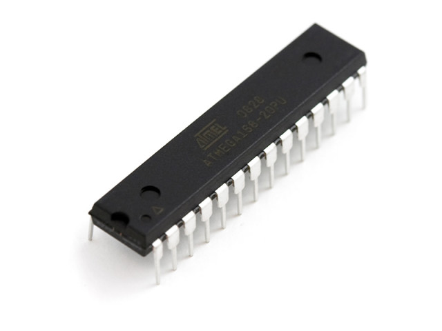
Chip for the QCX+ CW Transceiver kit, version 1.09a. This is an ATmega328 chip. This chip is compatible with all versions of the QCX including all PCB revisions of the original classic QCX, the QCX+ a..
$8.79
50W PA for QCX-series
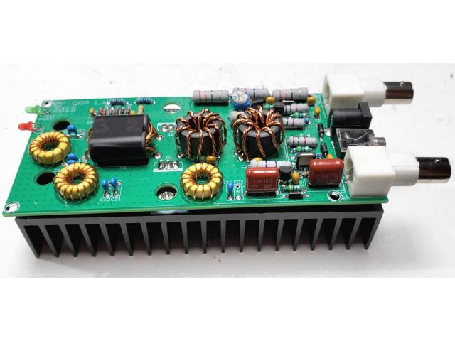
This 50W Power Amplifier kit can be built for any single band of 80m, 40m, 30m or 20m using the supplied components. There are no Surface Mount Components (SMD) to solder. A suitable power supply e.g...
$29.50
50W QCX PA kit enclosure
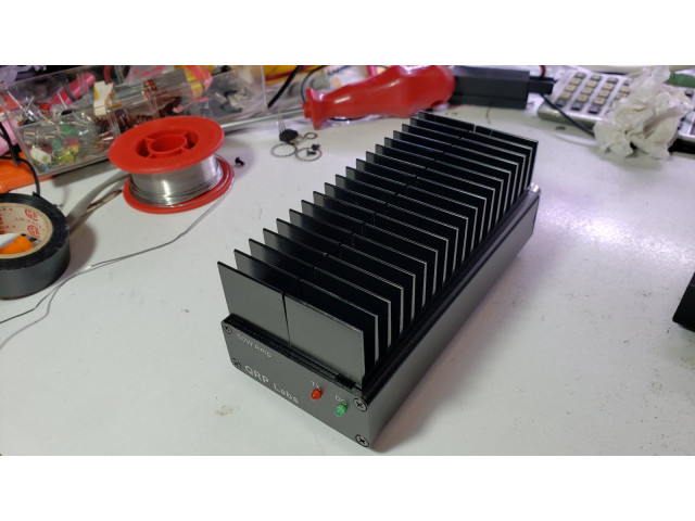
The 50W QCX PA kit case is made from black anodised aluminium, dimensions 63w x 25h x 130d mm. It's a 4-part case comprising front panel, back panel, top half and bottom half. The 4 parts are held tog..
$22.00
QCX+ Enclosure
This optional enclosure for the QCX+ 5W CW Transceiver kit is very sturdy and elegant. The front panel is 106 x 55mm and the depth is 146mm. It is custom-manufactured using extruded aluminium profiles..
$25.00
QCX+ Dev Board
The QCX+ development board kit is for anyone who wishes to experiment or modify their QCX+. The development board kit consists of a kit of parts including a PCB with the following features: High..
$9.00
QCX-mini Enclosure
This optional enclosure for the QCX-mini 5W CW Transceiver kit is very sturdy and elegant. The top panel is 95 x 63mm and the depth is 25mm. It is custom-manufactured using extruded aluminium pro..
$20.00
TCXO
The 25MHz TCXO module option provides frequency accuracy and stability to your QCX+, QCX-mini or other QRP Labs kits (including Ultimate3S). This is a tiny, ready-assembled PCB measuring 14.8 x 10...
$8.25

