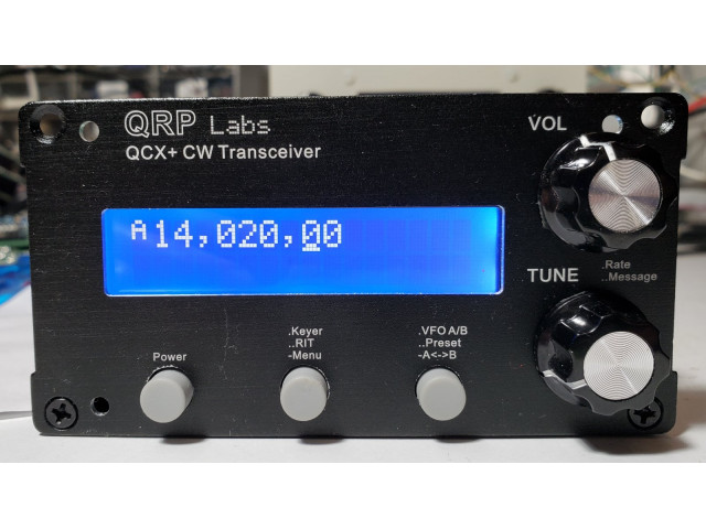
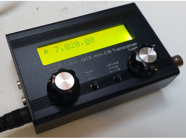
The "QCX+" (QRP Labs Xcvr +): a feature-packed, high performance, single band 5W CW transceiver kit with WSPR beacon and built-in alignment and test equipment. Available for 160, 80, 60, 40, 30, 20 or 17m bands. Experimental use on 15, 12, 10 or 6m (lower power output and reduced sensitivity). For complete details see http://qrp-labs.com/qcxp
NOTE: Assembled kits are built to order, the waiting list is published here https://www.qrp-labs.com/qcxmini/assembled.html - we ship around 25 per week so, if you are ordering an Assembled radio, please accept some waiting time based on this; if you need it urgently then please contact us about it.Assembled transceiver: This product is available as an
assembled, calibrated, adjusted and tested radio or as a KIT. Assembled
transceiver orders are built to order and please expect some waiting time (see above). If you order the TCXO or AGC options in the same
order, it will be installed in the transceiver and calibrated by us. If
you order the enclosure option in the same order, we will install the
transceiver into the enclosure. Any other options will be delivered as
KITS not assembled tested items.
The Optional enclosure is black anodized extruded aluminium, very sturdy and elegant. Front panel is 106 x 55mm and the depth is 146mm. The front and rear panels are drilled and cut to match the QCX+ with laser-etched lettering. The enclosure includes four self-adhesive feet.
Optional Dev Board kit is pictured above (diagram only, as yet) in one of the above photographs and is described further below.
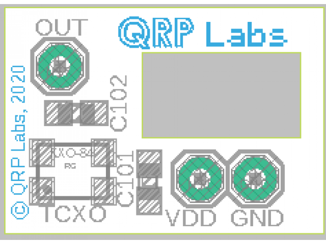
Optional 25MHz TCXO module is pictured above (diagram only, as yet). In tests, the frequency change over the range 4C to 65C was +/- 0.25 ppm (parts per million). This is a tiny 14.8 x 10.5mm PCB with TCXO, SMD all ready-assembled, which is installed onto the main QCX+ PCB in place of the 27MHz crystal and 0.1uF capacitor C2. The TCXO gives very good frequency stability if you intend to use WSPR operation, where frequency drift is critical. It is highly recommended for WSPR operation, particularly if you are using a 17m or 20m radio.
Morserino M32 Pocket is a highly popular Morse code trainer, see http://qrp-labs.com/morserino for details.
Hard-copy assembly instructions are not included in the kit. You need to download the assembly and operating instructions manual from http://qrp-labs.com/qcxp
Note: The QCX+ transceiver is always shipped with the latest firmware version available at the date of shipment.
Note: the optional GPS receiver module kit is very useful if you wish to operate this kit as a WSPR beacon (it disciplines frequency, time, and Maidenhead Locator grid square). It is also useful for calibrating the transceiver kit, to get the synthesizer reference oscillator precisely calibrated (resulting in accurate transmit/receive frequency).
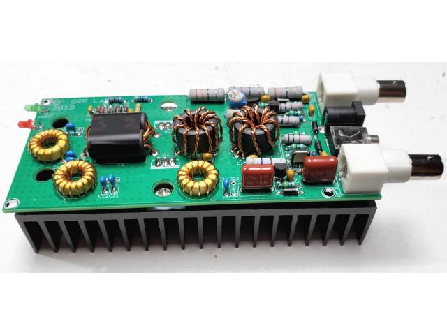
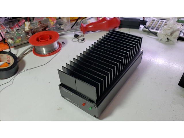
An optional 50W PA kit is available, which also has an optional enclosure. This 50W PA kit will give your QCX an extra boost for those occasions when you need a bit more power - to work a particular station for a regular sked when conditions are bad; to deal with our bad band conditions these days; to work a particular DX staiton, etc etc. The 50W PA kit includes solid state Tx/Rx switching for full break-in (QSK) operation. The kit includes heatsinks and connectors as well as the PCB and all components. See http://qrp-labs.com/50wpa for more details.
QCX-series radios do not have AGC built-in. An AGC module is listed as an option.
List of features:
- Easy to build, two-board design, spacious 10 x 13cm board with main circuit and connectors, vertical front panel board with LCD and all-controls board-mounted
- Professional quality double-sided, through-hole plated, silk-screen printed PCB
- Choice of single band, 160, 80, 60, 40, 30, 20 or 17m
- Approximately 3-5W CW output (depending on supply voltage)
- 7-16V recommended supply voltage
- Class E power amplifier, transistors run cool… even with no heatsinks
- 7-element Low Pass Filter ensures regulatory compliance
- CW envelope shaping to remove key clicks
- High performance receiver with at least 50dB of unwanted sideband cancellation
- 200Hz CW filter with no ringing
- Si5351A Synthesized VFO with rotary encoder tuning
- 16 x 2 blue backlight LCD screen
- Iambic keyer or straight key option included in the firmware
- Simple Digital Signal Processing assisted CW decoder, displayed real-time on-screen
- On-screen S-meter
- On-screen real time clock (not backed up)
- Full or semi QSK operation using fast solid-state transmit/receive switching
- Frequency presets, VFO A/B Split operation, RIT, configurable CW Offset
- Configurable sidetone frequency and volume
- Connectors: 2.1mm power barrel connector, 3.5mm keyer jack, 3.5mm stereo earphone jack, 3.5mm stereo jack for PTT, 3.5mm stereo jack for CAT control, BNC RF output
- Built-in test signal generator and alignment tools to complete simple set-up adjustments
- Built-in test equipment: voltmeter, RF power meter, frequency counter, signal generator
- Beacon mode, supporting automatic CW or WSPR operation
- GPS interface for reference frequency calibration and time-keeping (for WSPR beacon)
- CAT control interface
- Optional 50W PA kit
- Optional aluminium extruded cut/drilled/laser-etched black anodized enclosure
Optional Dev Board kit
The development board kit is for anyone who wishes to experiment or modify their QCX+. The development board kit consists of a kit of parts including a PCB with the following features:
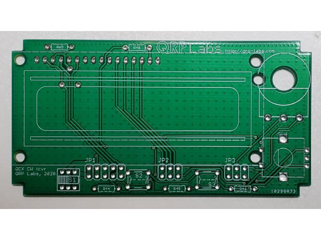
- High quality, double-sided PCB sized 95mm x 120mm (see PCB CAD exported diagram in the photos above)
- Through-hole plated holes with solder pads on top and bottom sides, on a standard 0.1-inch (2.54mm) matrix
- Ring of holes around the outside edge are all connected to ground
- Holes in the PCB are drilled to allow a screwdriver adjustment of the C1 trimmer capacitor, and the three trimmer potentiometers
- holes for fitting pin header connectors that mate with connectors on the main QCX+ PCB, for:
a) Power (Gnd, +5V, 12V)
b) Si5351A Clk0/1/2 outputs)
c) I2C bus
d) ISP header
e) Frequency counter, DVM and RF Power inputs
f) I and Q outputs (IC5 pin 1 and 7)
g) I and Q path phase shift outputs
h) CW filter input and output
i) Audio amplifier input and output
j) GPS header
k) CAT control and PTT signals
l) All pins of the PTT, CAT and Audio connectors
The dev kit consists of the following items:
- 95 x 120mm PCB
- 4pcs 12mm nylon hex spacer for mounting the PCB above the main QCX+ board
- 8pcs 6mm M3 nylon screw
- 8pcs 2-way female header connector
- 1pcs 20-way male header connector (may be broken into smaller pieces as desired)
Your imagination and dreams are not included!
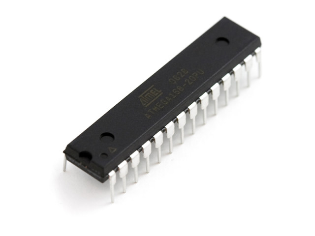
NOTE: 18-Dec-2021: The ATmega328 chip is now unobtainable at any distributors, due to the global semiconductor shortage. We have managed to obtain stock to be able to continue offering this item, however, the price was very high and this has necessitated a temporary price increase of $2.79 which is currently included in the price of this item.
QCX+ 5W CW transceiver
- Product Code: QCXP
- Availability: 209
-
$57.79
Available Options
Related Products
1.09a QCX/QCX+/QCX-mini upgrade
Chip for the QCX+ CW Transceiver kit, version 1.09a. This is an ATmega328 chip. This chip is compatible with all versions of the QCX including all PCB revisions of the original classic QCX, the QCX+ a..
$8.79
50W PA for QCX-series
This 50W Power Amplifier kit can be built for any single band of 80m, 40m, 30m or 20m using the supplied components. There are no Surface Mount Components (SMD) to solder. A suitable power supply e.g...
$29.50
50W QCX PA kit enclosure
The 50W QCX PA kit case is made from black anodised aluminium, dimensions 63w x 25h x 130d mm. It's a 4-part case comprising front panel, back panel, top half and bottom half. The 4 parts are held tog..
$22.00
QCX+ Enclosure
This optional enclosure for the QCX+ 5W CW Transceiver kit is very sturdy and elegant. The front panel is 106 x 55mm and the depth is 146mm. It is custom-manufactured using extruded aluminium profiles..
$25.00
QCX-series AGC module
AGC module for the popular QCX-series CW transceivers. This AGC module can be fitted to any PCB revision of QCX (classic), QCX+ and QCX-mini. This small 19 x 16mm ready-assembled AGC module is ba..
$6.00
QCX-mini Enclosure
This optional enclosure for the QCX-mini 5W CW Transceiver kit is very sturdy and elegant. The top panel is 95 x 63mm and the depth is 25mm. It is custom-manufactured using extruded aluminium pro..
$20.00
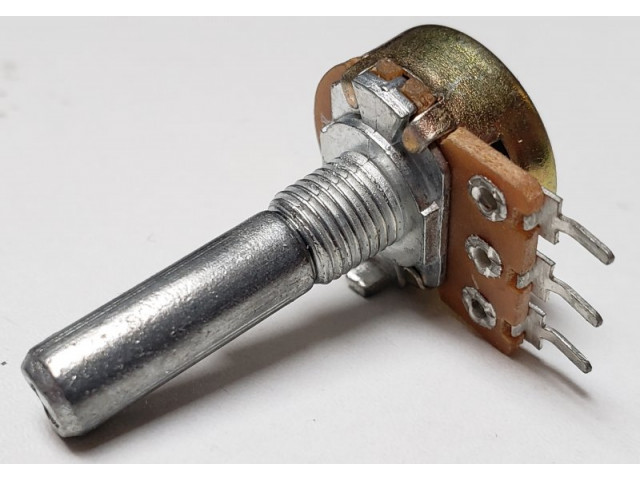
QCX+ 5K Potentiometer
5K Potentiometer for the QCX+ CW transceiver kit. Includes washer and nut (not pictured). ..
$2.50
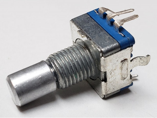
Rotary encoder
Rotary encoder used in QMX, QCX+, QCX-mini, and VFO kits. Includes washer and nut. ..
$2.00
TCXO
The 25MHz TCXO module option provides frequency accuracy and stability to your QCX+, QCX-mini or other QRP Labs kits (including Ultimate3S). This is a tiny, ready-assembled PCB measuring 14.8 x 10...
$8.25
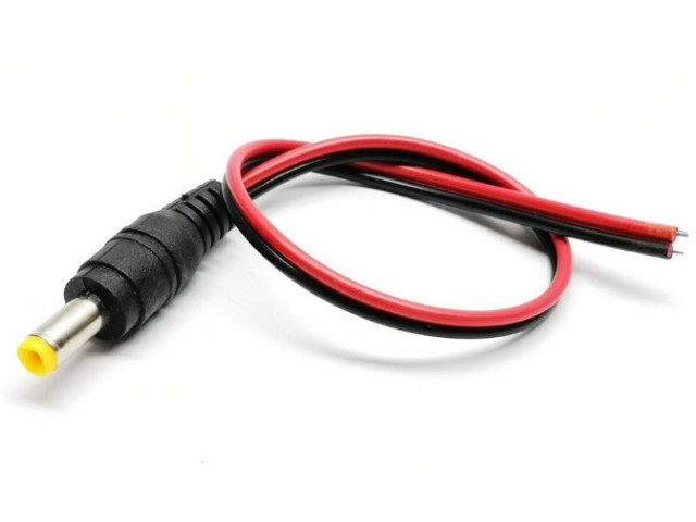
2.1mm power plug 20cm cable
A 2.1mm power plug with 20cm cable attached. Suitable for QRP Labs kits:QCX-miniQCX+ QDXQMX ..
$1.00
Blank large enclosure
This is an enclosure with blank (un-drilled, un-printed) front and rear panels, that is exactly the same size as the QCX+ and QMX+ enclosures. The front panel is 106 x 55mm and the depth is 146mm. It ..
$25.00
Morserino M32 Pocket
Morserino M32 PocketThe QRP Labs Morserino-32 Pocket is designed by Willi OE1WKL (with immense help by Hari OE6HKE and other contributors) and produced by QRP Labs under license. M32 Pocket is the thi..
$80.00

