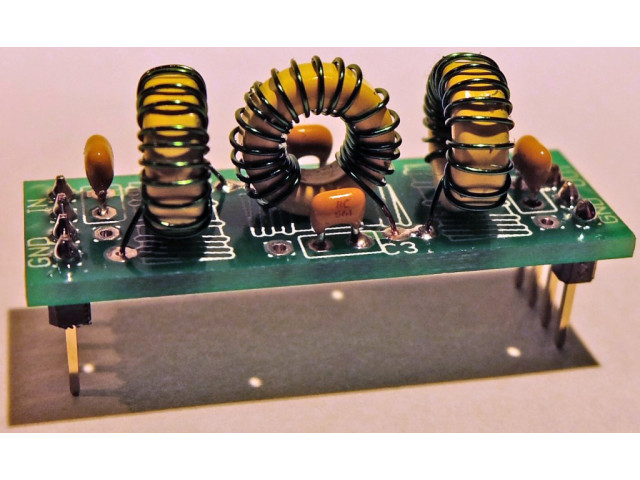
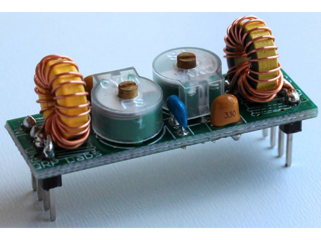
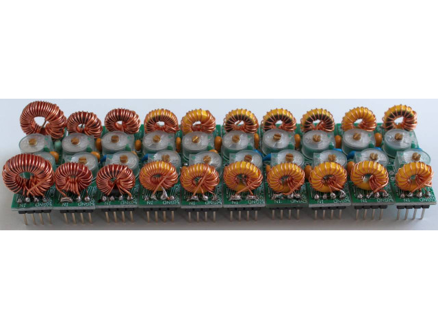
This Low Pass Filter (LPF) kit is based on the G-QRP technical pages design by Ed Whetherhold W3NQN. Kits are available for 16 bands 2200, 600, 160, 80, 60, 40, 30, 20, 17, 15, 12, 10, 6, 4, 2m and 222MHz. The kit uses a high-quality double-sided PCB with silk-screen, solder-mask and through-hole plating. The capacitors supplied with the kit are high-quality RF ceramics of the C0G type (a.k.a. NP0 - near-zero temperature coefficient).
NOTE: the 222MHz kit is supplied as "2m", only the number of inductor turns is different. Please refer to the assembly manual for details.
The LPF kit is designed to plug in to the Ultimate2 and Ultimate3 and Ultimate3S QRSS/WSPR kits.
Printed instructions are NOT supplied with the kit. You can download the kit-building instructions for your PCB from the links below. PCB revision 1 has nothing written on the PCB. Revision 2 has "Rev 2" written on the PCB silk-screen in two places. Please download the instructions from the LPF kit page.
LF band (600m and 2200m) kits:
Please see special notes in the instructions relating to the 600m and 2200m kits. There are many turns on the inductors in these LF kits and they cannot fit on the toroid. I did some measurements to determine whether the theoretical number of turns needs to be modified when the turns are wound messily on top of each other. The conclusion was that they do NOT.
The chart below shows measured inductance plotted against number of turns. The line is a rather imperfect curve since removing turns also resulted in some bunching and de-bunching of the remaining turns. The blue line is the theoretically predicted inductance. Note that the specification of the toroid permeability has a +/-5% tolerance and the difference between measured and theoretical values here is within 5%.

The following are photos of two coils I made for measurement while producing the above chart. I hope that they illustrate my winding method - just bunching all the turns on top of each other seems to work fine without damaging the predicted inductance. I think that the important thing is to wind evenly around the core - so that for example, the 48'th turn is near to the 52'nd and so on. But the 75'th turn of a 100-turn coil should be 90-degrees away from the 50'th turn.
The left photo is a 70-turn inductor for a 600m filter, and the right photo is a 105-turn inductor for a 2,200m filter. Please click the photos to open up a larger version!
Components and performance
The components provided in this LPF kit are tested and selected for good RF performance, to ensure minimum loss below the cut-off frequency and good attenuation outside it.
Capacitors: the provided capacitors are low-loss Class-1 dielectric RF types (also known as CC4), with low temperature coefficient (also known as NP0 or C0G). All the capacitors supplied have a voltage rating which is adequate for up to 10W RF.
Toroidal formers: Kits supplied from January 2014 onwards use toroids manufactured by a Micrometals competitor. These are more easily available outside the US. However, in order to ensure continued high quality and performance of the kits, the characteristics of these toroids, and the performance of the resulting LPF's have been extensively tested in 10m, 80m and 160m versions of the LPF kit (for T37-6, T37-2 and T50-2 toroids respectively).
For further information see the LPF kit page.
Low Pass Filter kit
- Product Code: LPF
- Availability: 1587
-
$4.60
Available Options
Related Products
Band Pass Filter kit
This Band Pass Filter (BPF) kit is for receiver input filtering. It uses the popular double-tuned-circuit which is reliable and easy to build, without needing access to any special equipment..
$4.90
Band Pass Filter kit set
This item is a set of 10 band pass filters (BPF), one for each of the HF bands 160, 80, 60, 40, 30, 20, 17, 15, 12 and 10m. The filters are designed for receiver input filtering and use the ..
$49.00
50-ohm 20W Dummy Load
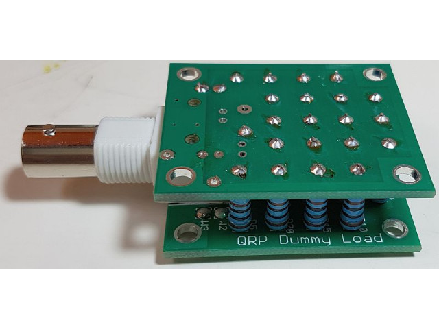
This useful shack accessory is a 50-ohm QRP dummy load kit. Features: 20 1K 1W 1% resistors in parallel make a 20W dummy load Peak voltage detector, for power measurement using a DVM BNC con..
$8.50
HF Sinewave VFO/SigGen set
This is a set of all the kits you need to build the sinewave output signal generator described in App Note AN006. Using VFO kit firmware s1.03 or above, the firmware can operate the VFO/SigGen kit wit..
$79.59
10W HF Linear PA
10W HF Linear Power Amplifier. Comfortably produces 10W from 12V supply. Compact design with huge heatsink included, which will not overheat even on continuous 100% duty-cycle operation. 26dB gain wit..
$26.00
ProgRock2 kit
A programmable crystal replacement. It has three independent outputs with frequency range 3.5kHz to approx 300MHz, and can be optionally GPS disciplined. Configuration is by a micro-USB connector and ..
$18.00

